
Electric Car Battery Charger Schematic Wiring Diagram
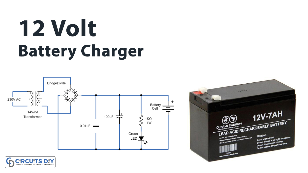
Simple 12 volt battery charger circuit diagram designed by using few easily available components, and this circuit is suitable for different types of batteries needs 12 Volt. You can use this circuit to charge 12V SLA battery or 12V Gel cell battery and so on. This circuit is designed to provide charging current upto 3 amps and this circuit don't have reverse polarity protection or over.
[DIAGRAM] Wiring Diagram For A Battery Charger
These C1 and C2 capacitors are acting as a filter in this circuit the LED indicates the presence of a DC power supply at the output. Connect the target Battery at the output to get charged. This is the circuit of a simple 12-volt battery charger for a lead-acid battery. It gives 12 volts and 5 Amps current for quick charging of the battery.

12v 7ah Battery Charger Circuit Diagram Pdf bestuload
Battery charger circuit applications are ideally suited with this IC and we are going to study one example circuits for making a 12 volt automatic battery charger circuit using the IC LM338. Referring to the circuit diagram we see that the entire circuit is wired around the IC LM301, which forms the control circuit for executing the trip off.
12 Volt Battery Charging Circuit Diagram
Page 8: Charging Battery Installed In Vehicle 12. After use clean, then store the charger indoors out of children's reach. Page 8 For technical questions, please call 1-800-444-3353. Item 60581. Page 9 Immediately disconnect the cables and connect as far away from battery as practical. them properly to prevent damage to the battery. 11.
need help in designing PWM 12v lead acid battery charger Forum for Electronics
12V battery charger circuit. Circuit diagram of the 12V battery absorb and float charger is shown in Fig. 1. It is built around step-down transformer X1, adjustable voltage regulator LM317 (IC1), op-amp comparator LM358 (IC2) and a few other components. The 230V AC primary to 15V-0-15V, 1A secondary transformer used in this circuit steps down.
12 Volt battery charger circuit diagram
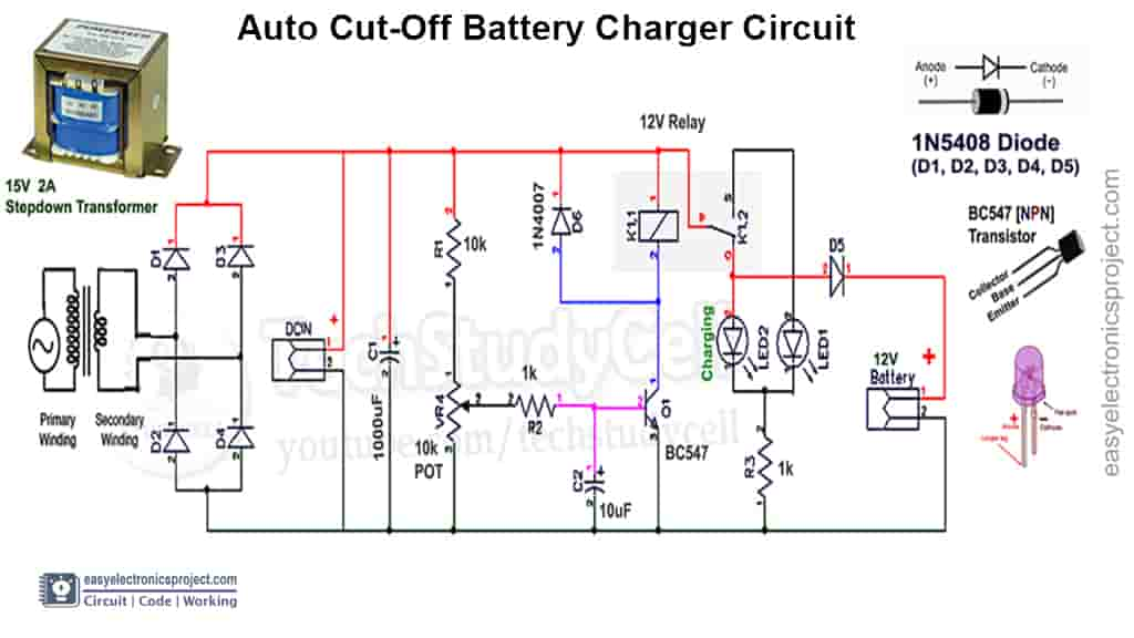
12v Battery Charger circuit with Overcharge Protection This 12-battery charger circuit provides an Automatic cut-off facility when the battery gets fully charged. Before the use of this circuit, you need to adjust the Cut off-voltage range for the auto cut. This adjustment is done by the moving 10k preset and for testing of output voltage..

Schematic 12v Battery Charger Circuit With Overcharge Protection Wiring Flow Line
This circuit can change the battery voltage of 3 sizes 6V, 9V, 12V. We can change each value parts as a neat charged battery. In a normal circuit, we use with 12V battery. For example, Look at the chassis battery is stated as 12V 20AH. The meaning is this can power the currents of 20 amps per hour.

Automatic 12v Battery Charger Circuit Auto Cut OFF & ON TechSaw
A battery can produce a short circuit current high enough toweld a ring (or the like) to metal, causing a severe bum. • Take care not to drop any metal tool or metal object onto the battery. This may spark or short circuit the battery or another electrical device that may cause an explosion. • Always operate your battery charger in
12 Volt Battery Charger Circuit Diagram Pdf Wiring Diagram
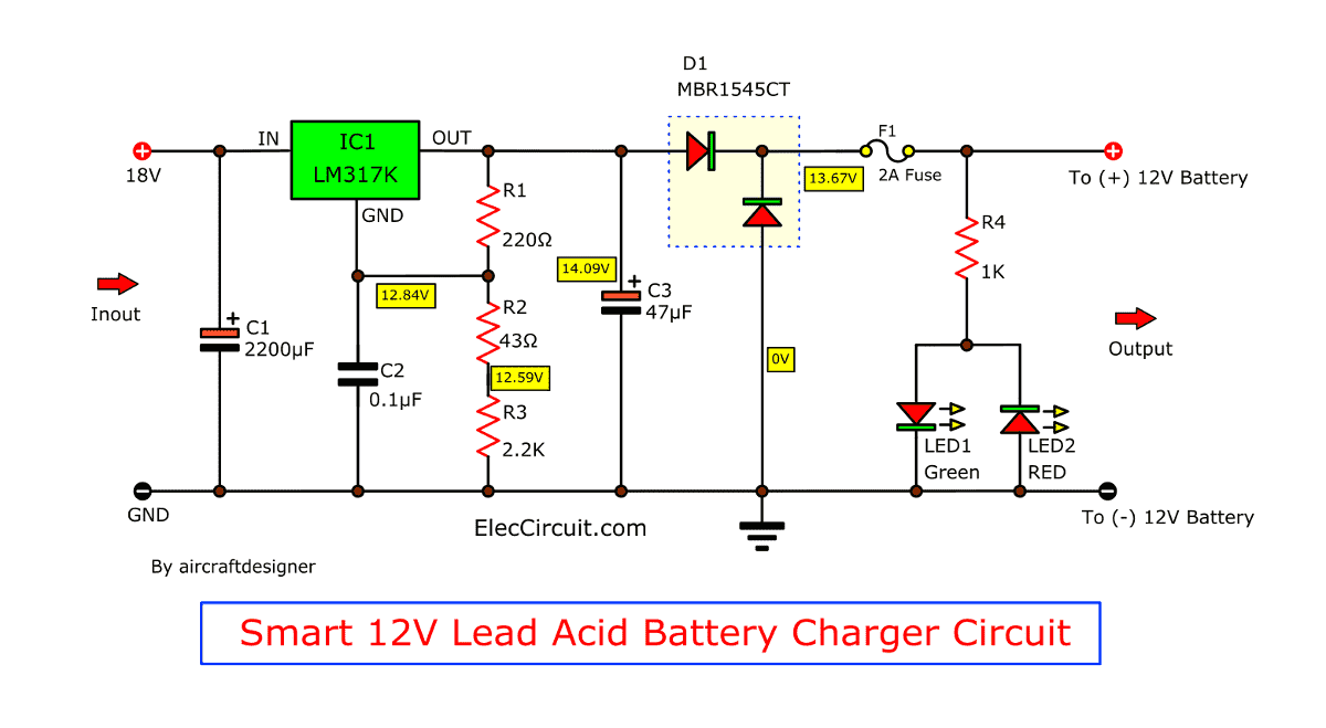
H ere is the circuit diagram of a simple and straight forward 12 V battery charger circuit with diagram. This circuit can be used to charge all type of 12V rechargeable batteries including car batteries. The circuit is nothing but a 12V DC power supply with an ammeter for monitoring the charging current. The two diodes forms a centre tapped.
Motorcycle Battery Charger Circuit Diagram Wiring Digital and Schematic
12v Battery charger Circuit Diagram : I designed a Circuit Diagram From Easy Eda Site. Components Needed :. Gerber & PDF Files : PCB_File Download. Gerber File Download. Make Video : Post Views: 29,186.. Since at first the full led turns on at 9.3V and the charging one turns on at 12.8V, which does not stop charging the battery, giving an.

Diagrama de circuito de cargador de batería simple de 12 voltios Progetto 7 lune
A 12V battery shows 14.4V on DMM when fully charged, so set 14.4V on the power supply. Adjust the 10K variable resistor until the green LED glows. To adjust the circuit for 6V batteries, replace the Zener diode with a 3V Zener diode. Set 7.2V on the adjustable power supply because a fully charged 6V battery shows 7.2V on DMM.

[36+] 12 Volt Automatic Battery Charger Circuit Diagram
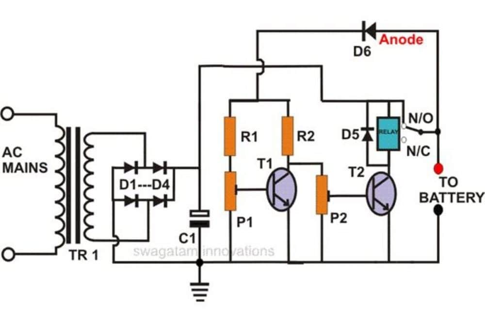
10 amp battery charger circuit diagram Circuit 2. Connect positive output wire on NC through Common pin of Relay. Circuit 3. This circuit has a maximum current capacity of 1 A only. Also read. Delay Timer To Switch ON / Switch OFF. LED Chaser Flasher Circuit. Automatic water level controller. 230v ac to 12v dc and 5v dc Regulated Power Converter

12 Volt 7 Amp Battery Charger Circuit Diagram Wiring Diagram
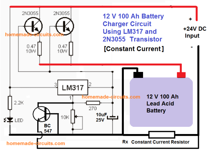
The main objective of our 12V power supply circuit is to control the voltage and current for the battery so that it can be charged in the best possible way. For this purpose we have used two LM317 ICs, one is used to control the voltage and the other is used to limit the current. Here, in our circuit the IC U1 is used to control the current and.

12 Volt battery charger circuit diagram
This simple 12-volt Battery Charger Circuit provides an outline design for a general battery charger, and you can add features like reverse polarity protection to this circuit by placing a diode at the output. (Diode anode to output positive supply and diode cathode as output positive terminal) and transistor-based overcurrent protection.

12 Volt 12 Amp Battery Charger and Maintainer OzCharge PRO1200
The working of this circuit is explained below. LM317 acts as voltage regulator and current controlling device. The 15V Zener diode is used to set the LM317 to supply 16.2V at output in the absence of load. When the 2N4401 is turned ON by the output of 555, the ADJ pin of the LM317 is grounded and its output voltage is 1.3V.
Motorcycle Battery Charger Circuit Diagram Wiring Diagram and Schematics
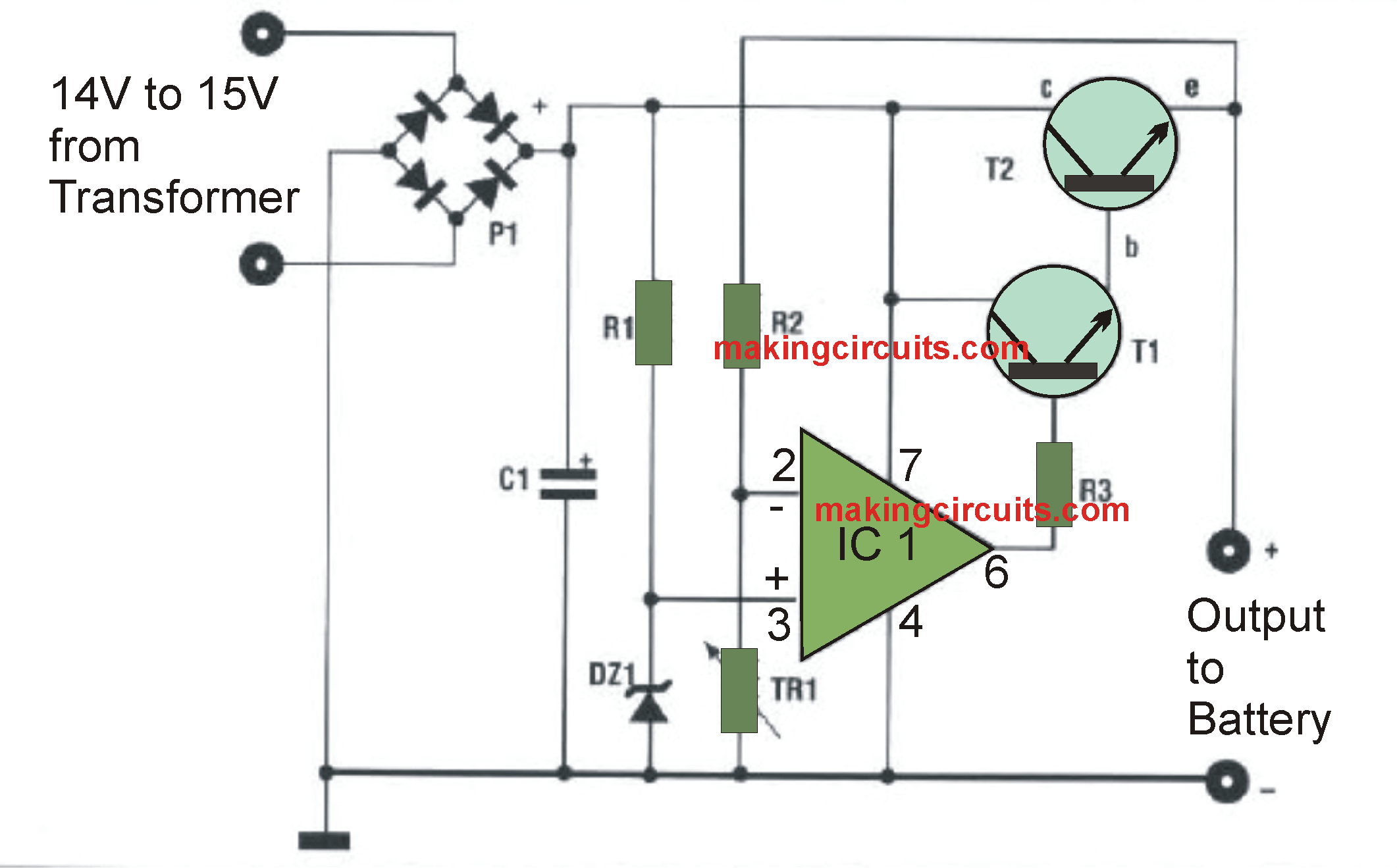
Printed circuit, AUTOMATIC BATTERY CHARGER INPUT 14-15 VOLTS at a charging CURRENT of MAX 3 AMPERES. Parts List for the 12V automatic car battery charger circuit: All resistors are. Of 1/4 watt unless otherwise specified. Rl-470 Ohms. R2 = 10 K. R3 = 270 Ohms. TR1 = 10 K trimmer. Cl = 1000uF25V.